Monthly Archives: January 2011

I’m currently attending the linux.conf.au conference here in Brisbane, Australia.

This morning, Vint Cerf spoke about the direction of the general Internet, and during Q&A, an audience member asked about bufferbloat.

I didn’t know what this  bufferbloat was, so I did a bit of reading, and found this.

In September of 2009, Dave Reed reported very long RTT’s with low packet loss on 3g networks on the end-to-end interest mailing list.  I’ve observed on several different operator’s 3g networks RTT times of order 6 seconds: Dave reported seeing up to 30 second RTT’s. These RTT’s are so long that many of the operations “time out”, by boredom (and extreme frustration) of the user.

Essentially, the explanation of bufferbloat is quite simple. The Internet revolves around the use of the transmission control protocol (TCP), which manages the rate at which nodes on the network send data by using congestion control techniques, such as exponential back-off. This works by monitoring when the network drops packets. If your computer notices that packets are being dropped, it is assumed that this is because of network congestion, and reduces the rate at which it sends new packets. Where the term bufferbloat comes in is buffers at various points in the network (several places in your computer, in your wireless router, in your ISP’s routers, the list goes on…) are getting larger, which confuses the TCP congestion control mechanisms, and creates huge queues of packets at all points in the network, giving rise to huge latencies.

Personally, I have experienced these problems on a daily basis using Vodafone’s 3G network.

If you’re interested in this problem, read more of Jim Gettys’ blog. If you work for Vodafone, please pass this information on.

[Edit] The description that David Reed gave of the problem on AT&T’s network is available here, the subsequent thread of conversation is an interesting dialog into TCP congestion control.
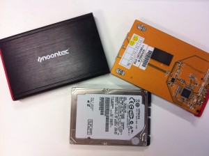
pic of hard drive and enclosure in piecesI recently purchased an external USB hard drive enclosure for a 2.5″ SATA disk drive.

It came with a USB cable with two ‘heads’, presumably because the hard drive might draw more current than a single USB port is specified to provide (500mA or 2.5W @ 5V).

In the past, I’ve done measurements on 2.5″ hard drives, and found that they draw much less than 2.5 W even at spin-up (the drive is an Hitachi 5400 RPM model). At idle, the drive consumes  about 400 mW and when spun-down, about 100 mW. At spin-up the power consumption surges to about 900 mW, then drops back to 400 mW.

Surely then, this external enclosure could power this 2.5″ hard drive from a single USB port? Not so. It turns out that the circuitry inside the enclosure draws a significant amount of power. About 900 mW to be exact. I went on a search to figure out why…

The enclosure is based around a Sunplus SATAlink SPIF215A single-chip USB->SATA controller. Looking at it’s datasheet, it’s supposed to draw a maximum of about 310mW from 3.3V and 1.8V rails, provided by a EMP5523 dual-output linear regulator.

There are also 3 (read it, three) bright blue LEDs to show you that the enclosure is powered up. Two of the LEDs had 100 ohm current-limiting resistors, and the third a 1 Kohm resistor. The two LEDs with 100 ohm resistors consume ~120mW of power alone.

A single USB port on my desktop machine was unable to provide enough power to spin up the hard drive until I unsoldered the two brightest LEDs leaving a single not-quite-so-bright LED to tell me when my hard drive enclosure is on. The hard drive now spins up.

What’s the lesson here? Poorly designed electronic devices consume a crazy amount of power. Low-efficiency linear regulators waste power too. When I’m using this external drive on my Laptop, I want it to consume as little power as possible so that my battery lasts as long as possible!